分类 无线电 下的文章

        结合domoticz系统的构建,2018年在楼顶安装了家用气象站,气象站采用一套HAM友提供的套件,弃用其温度百叶箱(内含主控)及无线液晶屏等显示部件,保留套件中风向风速传感器及雨量传感器,增加一个百叶箱,用BM280测量温湿度与气压,用一块NODEMCU作为主控芯片,测量计算风向风速雨量等信息,通过2.4G无线局域网向Domoticz和OneNET发送数据。这一版气象站问题还是不少的,最大的问题是架设在屋顶,与家里路由器隔了一个带有屏蔽作用的钢筋混凝土的屋顶,WIFI连接十分不稳定,经常出现掉线的情况,想了很多办法,包括在阳台增设无线中继放大器等,始终无法彻底解决连接不稳定问题,曾经考虑过改用有线联网,但气象站的百叶箱太小,放不下ethernet模块和POE模块,加之感觉这套系统中风向风速等传感器的技术比较玩具,例如风向是八个干簧管,通过串接不同阻值电阻指示八个方向,无法准确测量风向,风速是风杯旋转时干簧管通断产生脉冲信号等,雨量传感器虽然采用的是翻斗式的设计,但其受雨口并未按照国标设计等,也就凑合用了下来。
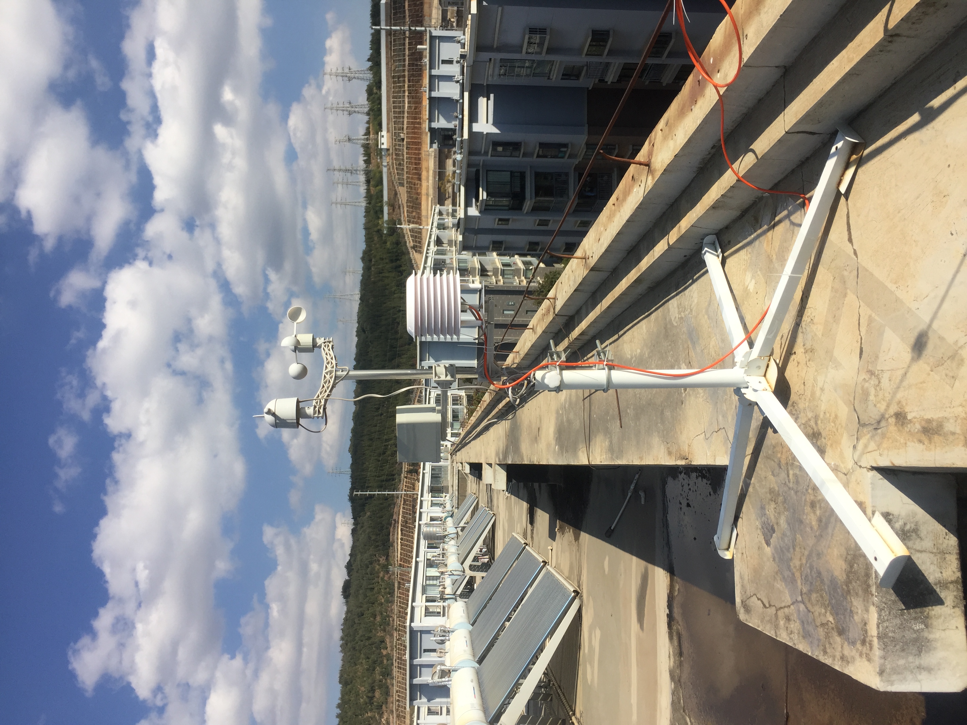
微信图片_20240311084953.jpg

        最近这套系统彻底没数据了,断电重启也无效,这才下定决心进行换版重制。这次选用RS485接口的气象站组件,内置了温湿度气压,以及超声波风向风速传感器,还有一个光学雨量传感器。超声波测量风向风速似乎已经相对成熟,但采用光学方法测量雨量倒是没有想到,搜索了一番发现,似乎这也是一种得到承认的方法,那就试试吧。采用RS485组件的优点是一是数据读取方便,因其采用modbus协议,一个RS485设备可以集成多种传感器,只要发送指令读取每个传感器对应的寄存器数据即可,二是RS485传输距离长,一根RS485电缆从屋顶连下来,主控模块也可放在室内,防护更好,也方便后期调整升级固件。这次采用ethernet连接,不会再出现连接不稳定现象。
微信图片_20240311084931.jpg

        调试过程中的技术问题及解决要点如下:

  • Arduino的MODBUS RS485库有很多,作为主站控制的话,SensorModbusMaster是最好用的。虽然作者说这个库用于带自动收发的芯片,例如MAX13487的时候效果更好,但试验下来,如果只用9600这样波特率的话,MAX485芯片工作也完全正常。
  • RS485接口电路中AB之间的终端电阻是用于阻抗匹配的,用来减少反射,但是如果RS485接线本身不长的话,加上终端电阻反而是有害无益,调试时发现读取数据很不稳定,设置了8N1的串口协议有时候只能读出7bit数据,百思不得其解,去掉终端电阻就一切正常了。而且加上终端电阻后将大幅度拉低AB间电平,所以加不加,最好试验着看。
  • 有人串口ethernet模块如果出现发送的数据语法格式无误,但就是返回代码400的话,大概率是串口工作模式没有处在正确模式上,即发送数据时还处于命令模式,或发送命令模式时还处于数据透传模式,但是ethernet工作过程中可能会出现各种情况,编写程序时难以穷尽所有情况,所以一个讨巧的办法是在进入命令模式时先发送一遍进入数据透传模式,反之亦然,这样如果工作模式正确最多返回一条-1错误,不影响程序正常运行,但如果工作模式不正确,则正好可以纠正到程序设计模式上来,后续工作就一切正常了。

        domoticz总的来说是算稳定的开源系统,但自己增加功能势必遇到各种稀奇古怪的问题,domoticz中文区半死不活,domoticz.com访问又被拒绝,解决问题还是颇费时间。当然有些问题属于自己对raspbian还没有烂熟于心的缘故,raspberry pi遇到问题搜索大法不一定管用,国内搜索质量良莠不齐,很多解答随着软件版本的更新已失效,最高效的方式还是把问题转换为英文,在google上搜索往往第一页还没有翻完就找到答案。以下是一些记录备忘,此文将不定时更新。

  • raspberry pi的定时任务设置问题。经常遇到定时任务设置了但是没有起作用的情况,而且好像crontab在不同位置有不同文件,有的配置文件还与用户账号有关。试验下来,用这个命令没问题: crontab -e ,要想更保险一点,执行的脚本用绝对路径。修改完了后不要忘记sudo service cron restart重启服务。
  • domoticz的开关等可以设置开或关时触发动作,但语句开头必须是http://或https://或script://,执行脚本时语句格式是:

    scripts:///home/xx/xxx.../xxx.py
    scripts:///home/xx/xxx.../xxx.sh
    scripts:///home/xx/xxx.../xxx.lua

    等等,如果设置了执行脚本但是没有起作用,大概率是被执行脚本没有打开执行权限,脚本执行后日志中返回错误码32256或512都是这个问题,进入脚本目录执行sudo chmod +x XXX.pysudo chmod 755 XXX.py即可,如果还不行就写个sh脚本,把执行命令等写进去,设为执行这个sh脚本就可以,貌似用这个方法被执行脚本打开不打开执行权限都没有关系。

  • domoticz.com屏蔽国内IP后,官网论坛可以访问https://en.domoticz.cn/forum/,官网WIKI可以访问https://en.domoticz.cn/wiki/Main_Page。貌似国内的镜像站?

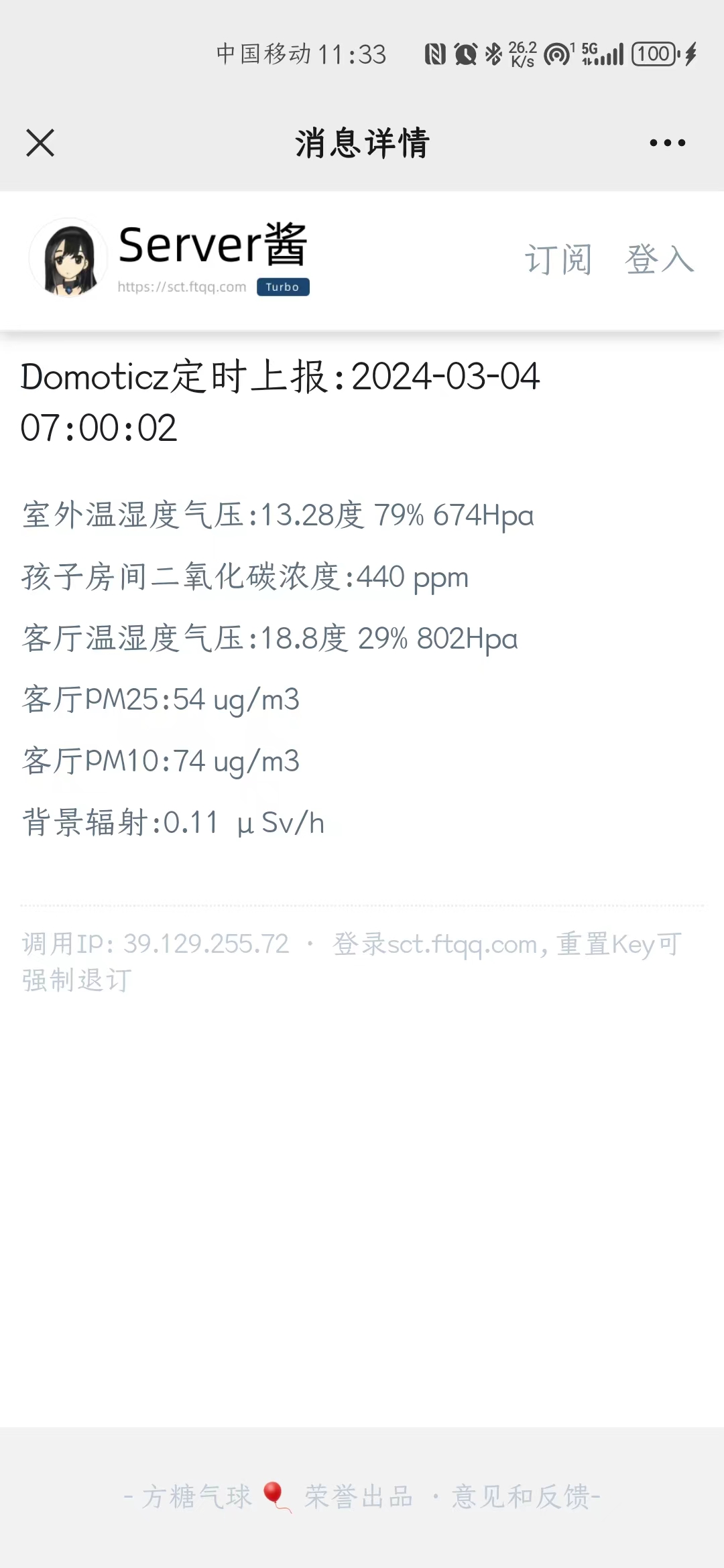
        往微信推送信息,Server酱是最方便的办法。注册,获得一个KEY,再在微信上弄个企业微信的链接,就可以通过post https://sctapi.ftqq.com/.send?title=short_title&desp=long_content来推送信息,SENDKEY是你的发送密码,title后面是推送标题,desp后面是推送内容,内容用markdown语法,可以是文字、图片、链接或者几者的混排,但它用的好像是commonmark.org的语法,有些通用写法它不一定认。你用什么语言POST都可以,当然用python是最方便。

        于是我:

用它来推中央气象台的各种气象图微信图片_20240304114327.jpg

用它来推定制的天气预报微信图片_20240304114336.jpg

用它来推domoticz的实时数据微信图片_20240304114318.jpg

用它来推前一晚流星监测站的监测结果微信图片_20240304114355.jpg

        总之想推什么推什么,用python写个简单的脚本抓取想要推送的信息,然后通过Server酱推送就好。把脚本丢到树莓派上,设个定时任务,就可以定时推送啦。

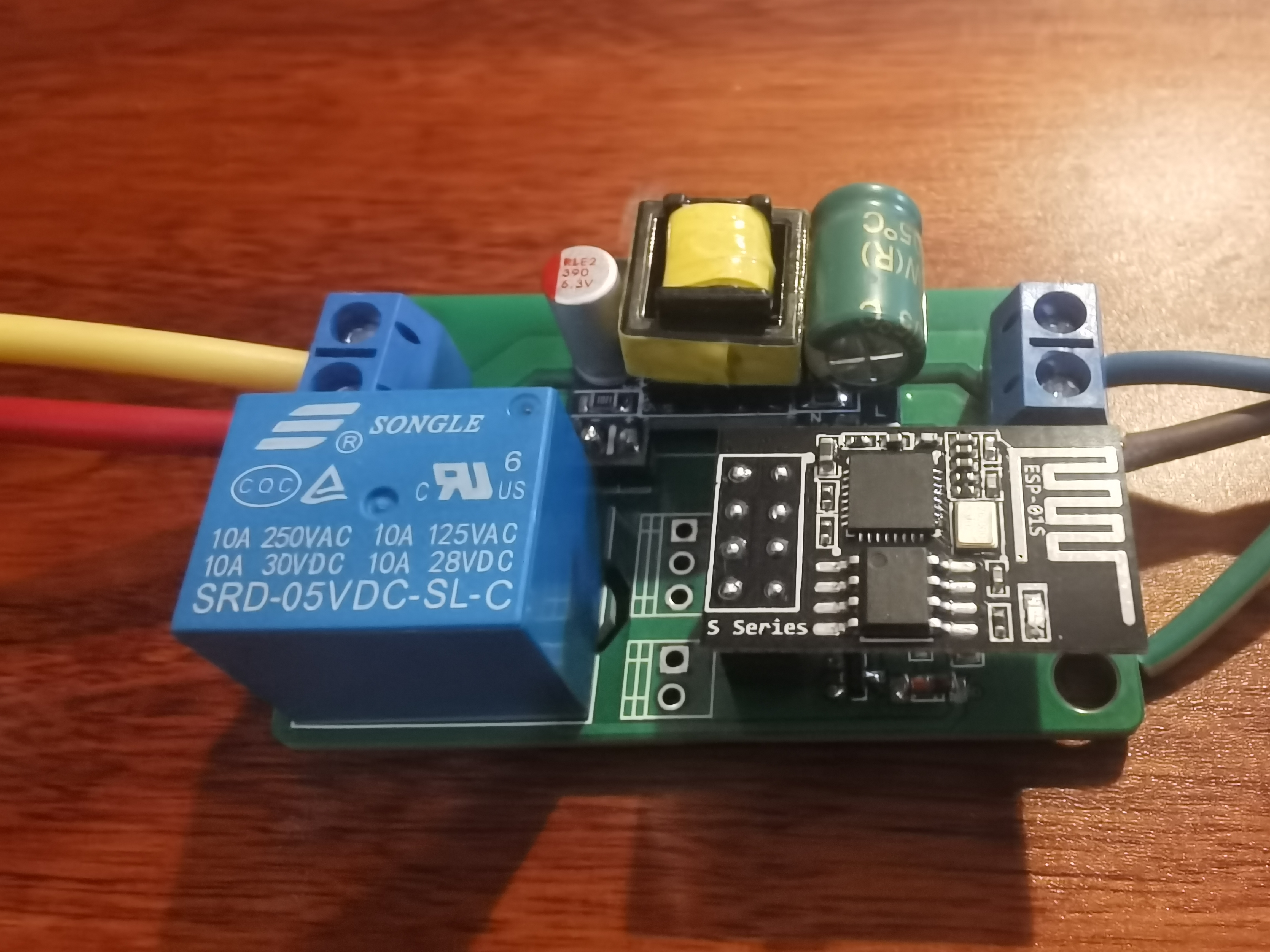
        Domoticz控制开关用ESP-01S是最方便的办法。ESP-01S烧录ESPEasy固件后,可以不用编程,仅仅经过简单设置就可以在Domoticz中使用。之前在淘宝买过ESP01继电器板,用来控制灯光等需要外接电源模块,颇为不便,最近看到https://www.instructables.com/Home-Automation-Using-ESP01/上的印刷电路板,设计科学,将电源模块也集成在电路板上,外接电器十分方便,下载印刷电路板图制作后,试验成功。有几年没有烧录ESPEasy了,一些步骤不太记得,费了一些功夫,把流程记录如下,以后再用也方便些。

  • 先下载ESPEasy固件和烧录器,最新版在https://github.com/letscontrolit/ESPEasy/releases,其中也有历史固件。不一定要下载最新版,要选择下载ESP8266系列的固件。
  • 将ESP-01S插在编程器上,烧录ESPEasy固件,注意要选择1M那个版本的固件,不能用4M1M版本的。
  • 烧录完毕后按编程器上的复位按钮,稍后在wifi列表中连接新出现的ESP_0的SSID,连接密码是configesp。
  • 浏览器会自动弹出配网窗口,如果没有弹出,在浏览器中输入192.168.4.1,进入配网界面,选择ESP-01S需要连接的网络SSID,输入密码保存。模块配网后会重启,显示模块的IP地址。如果没有显示,切换网络到局域网上,在局域网内寻找新联网设备,记录IP地址。
  • 在浏览器中进入模块IP地址,进行配置。模块配置可以看https://blog.csdn.net/lionwerson/article/details/104417481,其实最好是对比之前已经做好的配置进行配置。

        几点Tips:

  • 不同的继电器板有不同的控制逻辑,比如原来在淘宝上买的继电器板是低电平导通,网上这个继电器板电路则是高电平导通,如要上电即导通,则设置中“Hardware”中GPIO-0模式要设置为Output Low。
  • Domoticz增加新的开关要到设置-硬件中找到之前设置的Dummy,点“创建虚拟传感器”,选择传感器类型为开关,输入一个名字,在开关页面就可以看到新建的开关。
  • ESP-01S与ESP-01的区别是前者的IO口已经内置上拉电阻,不需要在电路板上再行设置,所以尽量选择ESP-01S。这个网站也讲了两者区别和ESPEasy的配置过程https://sancla.com/domoticz/esp8266-with-esp-easy/
  • 不同版本的easyesp烧录器各有不同,较新版本固件的烧录器除了要选择固件版本,还要选择烧录起始地址,地址选0x00000000即可。

微信图片_20240303230103.jpg

        esp32系列是高性价比物联网节点设备的代表,速度够快,自带WIFI又可以使用Arduino IDE编程,最近试用了一种带有OV2640摄像头的ESP32-CAM只要很简单地设置就可以做很多种工作,以下是试验记录。

        Arduino IDE要在首选项中在其他开发板管理器地址中填入https://raw.githubusercontent.com/espressif/arduino-esp32/gh-pages/package_esp32_index.json,再去开发板管理器界面中找到ESP32,点击安装后才能使用ESP32系列单片机。注意要联网才能安装。

  • 用作延时相机

    #include "esp_camera.h"
    #include "FS.h"                // SD Card ESP32
    #include "SD_MMC.h"            // SD Card ESP32
    #include "soc/soc.h"           // Disable brownout problems
    #include "soc/rtc_cntl_reg.h"  // Disable brownout problems
    #include "driver/rtc_io.h"
    #include <WiFi.h>
    #include "time.h"
    
    
    // REPLACE WITH YOUR NETWORK CREDENTIALS
    const char* ssid = "XXXXXX";
    const char* password = "XXXXXX";
    
    
    // REPLACE WITH YOUR TIMEZONE STRING: https://github.com/nayarsystems/posix_tz_db/blob/master/zones.csv
    String myTimezone ="CST-8";
    
    
    // Pin definition for CAMERA_MODEL_AI_THINKER
    // Change pin definition if you're using another ESP32 camera module
    #define PWDN_GPIO_NUM     32
    #define RESET_GPIO_NUM    -1
    #define XCLK_GPIO_NUM      0
    #define SIOD_GPIO_NUM     26
    #define SIOC_GPIO_NUM     27
    #define Y9_GPIO_NUM       35
    #define Y8_GPIO_NUM       34
    #define Y7_GPIO_NUM       39
    #define Y6_GPIO_NUM       36
    #define Y5_GPIO_NUM       21
    #define Y4_GPIO_NUM       19
    #define Y3_GPIO_NUM       18
    #define Y2_GPIO_NUM        5
    #define VSYNC_GPIO_NUM    25
    #define HREF_GPIO_NUM     23
    #define PCLK_GPIO_NUM     22
    
    
    // Stores the camera configuration parameters
    camera_config_t config;
    
    
    // Initializes the camera
    void configInitCamera(){
    config.ledc_channel = LEDC_CHANNEL_0;
    config.ledc_timer = LEDC_TIMER_0;
    config.pin_d0 = Y2_GPIO_NUM;
    config.pin_d1 = Y3_GPIO_NUM;
    config.pin_d2 = Y4_GPIO_NUM;
    config.pin_d3 = Y5_GPIO_NUM;
    config.pin_d4 = Y6_GPIO_NUM;
    config.pin_d5 = Y7_GPIO_NUM;
    config.pin_d6 = Y8_GPIO_NUM;
    config.pin_d7 = Y9_GPIO_NUM;
    config.pin_xclk = XCLK_GPIO_NUM;
    config.pin_pclk = PCLK_GPIO_NUM;
    config.pin_vsync = VSYNC_GPIO_NUM;
    config.pin_href = HREF_GPIO_NUM;
    config.pin_sscb_sda = SIOD_GPIO_NUM;
    config.pin_sscb_scl = SIOC_GPIO_NUM;
    config.pin_pwdn = PWDN_GPIO_NUM;
    config.pin_reset = RESET_GPIO_NUM;
    config.xclk_freq_hz = 20000000;
    config.pixel_format = PIXFORMAT_JPEG; //YUV422,GRAYSCALE,RGB565,JPEG
    config.grab_mode = CAMERA_GRAB_LATEST;
    
    
    // Select lower framesize if the camera doesn't support PSRAM
    if(psramFound()){
      config.frame_size = FRAMESIZE_UXGA; // FRAMESIZE_ + QVGA|CIF|VGA|SVGA|XGA|SXGA|UXGA
      config.jpeg_quality = 5; //0-63 lower number means higher quality
      config.fb_count = 1;
    } else {
      config.frame_size = FRAMESIZE_UXGA;
      config.jpeg_quality = 5;
      config.fb_count = 1;
    }
    
    // Initialize the Camera
    esp_err_t err = esp_camera_init(&config);
    if (err != ESP_OK) {
      Serial.printf("Camera init failed with error 0x%x", err);
      return;
    }
    }
    
    
    // Connect to wifi
    void  initWiFi(){
    WiFi.begin(ssid, password);
    Serial.println("Connecting Wifi");
    while (WiFi.status() != WL_CONNECTED) {
      Serial.print(".");
      delay(500);
    }
    }
    
    
    // Function to set timezone
    void setTimezone(String timezone){
    Serial.printf("  Setting Timezone to %s\n",timezone.c_str());
    setenv("TZ",timezone.c_str(),1);  //  Now adjust the TZ.  Clock settings are adjusted to show the new local time
    tzset();
    }
    
    
    // Connect to NTP server and adjust timezone
    void initTime(String timezone){
    struct tm timeinfo;
    Serial.println("Setting up time");
    configTime(0, 0, "pool.ntp.org");    // First connect to NTP server, with 0 TZ offset
    if(!getLocalTime(&timeinfo)){
      Serial.println(" Failed to obtain time");
      return;
    }
    Serial.println("Got the time from NTP");
    // Now we can set the real timezone
    setTimezone(timezone);
    }
    
    
    // Get the picture filename based on the current ime
    String getPictureFilename(){
    struct tm timeinfo;
    if(!getLocalTime(&timeinfo)){
      Serial.println("Failed to obtain time");
      return "";
    }
    char timeString[20];
    strftime(timeString, sizeof(timeString), "%Y-%m-%d_%H-%M-%S", &timeinfo);
    Serial.println(timeString);
    String filename = "/picture_" + String(timeString) +".jpg";
    return filename; 
    }
    
    
    // Initialize the micro SD card
    void initMicroSDCard(){
    // Start Micro SD card
    Serial.println("Starting SD Card");
    if(!SD_MMC.begin()){
      Serial.println("SD Card Mount Failed");
      return;
    }
    uint8_t cardType = SD_MMC.cardType();
    if(cardType == CARD_NONE){
      Serial.println("No SD Card attached");
      return;
    }
    }
    
    
    // Take photo and save to microSD card
    void takeSavePhoto(){
    // Take Picture with Camera
    camera_fb_t * fb = esp_camera_fb_get();
    
    //Uncomment the following lines if you're getting old pictures
    //esp_camera_fb_return(fb); // dispose the buffered image
    //fb = NULL; // reset to capture errors
    //fb = esp_camera_fb_get();
    
    if(!fb) {
      Serial.println("Camera capture failed");
      delay(1000);
      ESP.restart();
    }
    
    
    // Path where new picture will be saved in SD Card
    String path = getPictureFilename();
    Serial.printf("Picture file name: %s\n", path.c_str());
    
    // Save picture to microSD card
    fs::FS &fs = SD_MMC; 
    File file = fs.open(path.c_str(),FILE_WRITE);
    if(!file){
      Serial.printf("Failed to open file in writing mode");
    } 
    else {
      file.write(fb->buf, fb->len); // payload (image), payload length
      Serial.printf("Saved: %s\n", path.c_str());
    }
    file.close();
    esp_camera_fb_return(fb); 
    }
    
    
    void setup() {
    WRITE_PERI_REG(RTC_CNTL_BROWN_OUT_REG, 0); // disable brownout detector
    
    
    Serial.begin(115200);
    delay(2000);
    
    
    // Initialize Wi-Fi
    initWiFi();
    // Initialize time with timezone
    initTime(myTimezone);    
    // Initialize the camera  
    Serial.print("Initializing the camera module...");
    configInitCamera();
    Serial.println("Ok!");
    // Initialize MicroSD
    Serial.print("Initializing the MicroSD card module... ");
    initMicroSDCard();
    }
    
    
    void loop() {    
    // Take and Save Photo
    takeSavePhoto();
    delay(60000);
    }

            在程序中修改SSID、PASSWORD,myTimezone设置时区字符串,在https://github.com/nayarsystems/posix_tz_db/blob/master/zones.csv中查找到属于当地的时区字符串;config.frame_size设置拍摄分辨率,config.jpeg_quality设置图像质量,0~63,数字越小图像质量越高,但有可能造成图像拍摄出现问题。loop()中delay()函数内是延时时间。
            图像质量实在差劲,最高分辨率UXGA下图像质量设置为0时所拍照片偶有撕裂现象,我一般设置为5。模块上电后按一下reset键,可以确保系统正常工作。

  • 用作网络摄影机

    #include "esp_camera.h"
    #include <WiFi.h>
    
    //
    // WARNING!!! PSRAM IC required for UXGA resolution and high JPEG quality
    //            Ensure ESP32 Wrover Module or other board with PSRAM is selected
    //            Partial images will be transmitted if image exceeds buffer size
    //
    //            You must select partition scheme from the board menu that has at least 3MB APP space.
    //            Face Recognition is DISABLED for ESP32 and ESP32-S2, because it takes up from 15 
    //            seconds to process single frame. Face Detection is ENABLED if PSRAM is enabled as well
    
    // ===================
    // Select camera model
    // ===================
    //#define CAMERA_MODEL_WROVER_KIT // Has PSRAM
    //#define CAMERA_MODEL_ESP_EYE // Has PSRAM
    //#define CAMERA_MODEL_ESP32S3_EYE // Has PSRAM
    //#define CAMERA_MODEL_M5STACK_PSRAM // Has PSRAM
    //#define CAMERA_MODEL_M5STACK_V2_PSRAM // M5Camera version B Has PSRAM
    //#define CAMERA_MODEL_M5STACK_WIDE // Has PSRAM
    //#define CAMERA_MODEL_M5STACK_ESP32CAM // No PSRAM
    //#define CAMERA_MODEL_M5STACK_UNITCAM // No PSRAM
    #define CAMERA_MODEL_AI_THINKER // Has PSRAM
    //#define CAMERA_MODEL_TTGO_T_JOURNAL // No PSRAM
    //#define CAMERA_MODEL_XIAO_ESP32S3 // Has PSRAM
    // ** Espressif Internal Boards **
    //#define CAMERA_MODEL_ESP32_CAM_BOARD
    //#define CAMERA_MODEL_ESP32S2_CAM_BOARD
    //#define CAMERA_MODEL_ESP32S3_CAM_LCD
    //#define CAMERA_MODEL_DFRobot_FireBeetle2_ESP32S3 // Has PSRAM
    //#define CAMERA_MODEL_DFRobot_Romeo_ESP32S3 // Has PSRAM
    #include "camera_pins.h"
    
    // ===========================
    // Enter your WiFi credentials
    // ===========================
    const char* ssid = "XXXXXX";
    const char* password = "XXXXXX";
    
    void startCameraServer();
    void setupLedFlash(int pin);
    
    void setup() {
    Serial.begin(115200);
    Serial.setDebugOutput(true);
    Serial.println();
    
    camera_config_t config;
    config.ledc_channel = LEDC_CHANNEL_0;
    config.ledc_timer = LEDC_TIMER_0;
    config.pin_d0 = Y2_GPIO_NUM;
    config.pin_d1 = Y3_GPIO_NUM;
    config.pin_d2 = Y4_GPIO_NUM;
    config.pin_d3 = Y5_GPIO_NUM;
    config.pin_d4 = Y6_GPIO_NUM;
    config.pin_d5 = Y7_GPIO_NUM;
    config.pin_d6 = Y8_GPIO_NUM;
    config.pin_d7 = Y9_GPIO_NUM;
    config.pin_xclk = XCLK_GPIO_NUM;
    config.pin_pclk = PCLK_GPIO_NUM;
    config.pin_vsync = VSYNC_GPIO_NUM;
    config.pin_href = HREF_GPIO_NUM;
    config.pin_sccb_sda = SIOD_GPIO_NUM;
    config.pin_sccb_scl = SIOC_GPIO_NUM;
    config.pin_pwdn = PWDN_GPIO_NUM;
    config.pin_reset = RESET_GPIO_NUM;
    config.xclk_freq_hz = 20000000;
    config.frame_size = FRAMESIZE_UXGA;
    config.pixel_format = PIXFORMAT_JPEG; // for streaming
    //config.pixel_format = PIXFORMAT_RGB565; // for face detection/recognition
    config.grab_mode = CAMERA_GRAB_WHEN_EMPTY;
    config.fb_location = CAMERA_FB_IN_PSRAM;
    config.jpeg_quality = 5;
    config.fb_count = 1;
    
    // if PSRAM IC present, init with UXGA resolution and higher JPEG quality
    //                      for larger pre-allocated frame buffer.
    if(config.pixel_format == PIXFORMAT_JPEG){
      if(psramFound()){
        config.jpeg_quality = 5;
        config.fb_count = 2;
        config.grab_mode = CAMERA_GRAB_LATEST;
      } else {
        // Limit the frame size when PSRAM is not available
        config.frame_size = FRAMESIZE_SVGA;
        config.fb_location = CAMERA_FB_IN_DRAM;
      }
    } else {
      // Best option for face detection/recognition
      config.frame_size = FRAMESIZE_240X240;
    #if CONFIG_IDF_TARGET_ESP32S3
      config.fb_count = 2;
    #endif
    }
    
    #if defined(CAMERA_MODEL_ESP_EYE)
    pinMode(13, INPUT_PULLUP);
    pinMode(14, INPUT_PULLUP);
    #endif
    
    // camera init
    esp_err_t err = esp_camera_init(&config);
    if (err != ESP_OK) {
      Serial.printf("Camera init failed with error 0x%x", err);
      return;
    }
    
    sensor_t * s = esp_camera_sensor_get();
    // initial sensors are flipped vertically and colors are a bit saturated
    if (s->id.PID == OV3660_PID) {
      s->set_vflip(s, 1); // flip it back
      s->set_brightness(s, 1); // up the brightness just a bit
      s->set_saturation(s, -2); // lower the saturation
    }
    // drop down frame size for higher initial frame rate
    if(config.pixel_format == PIXFORMAT_JPEG){
      s->set_framesize(s, FRAMESIZE_QVGA);
    }
    
    #if defined(CAMERA_MODEL_M5STACK_WIDE) || defined(CAMERA_MODEL_M5STACK_ESP32CAM)
    s->set_vflip(s, 1);
    s->set_hmirror(s, 1);
    #endif
    
    #if defined(CAMERA_MODEL_ESP32S3_EYE)
    s->set_vflip(s, 1);
    #endif
    
    // Setup LED FLash if LED pin is defined in camera_pins.h
    #if defined(LED_GPIO_NUM)
    setupLedFlash(LED_GPIO_NUM);
    #endif
    
    WiFi.begin(ssid, password);
    WiFi.setSleep(false);
    
    while (WiFi.status() != WL_CONNECTED) {
      delay(500);
      Serial.print(".");
    }
    Serial.println("");
    Serial.println("WiFi connected");
    
    startCameraServer();
    
    Serial.print("Camera Ready! Use 'http://");
    Serial.print(WiFi.localIP());
    Serial.println("' to connect");
    }
    
    void loop() {
    // Do nothing. Everything is done in another task by the web server
    delay(10000);
    }

            在程序中修改SSID、PASSWORD,上传后打开串口监视器,按rst键,看模块IP地址,在浏览器中输入IP地址就进入网络摄像头界面,点Start Stream开始摄像头网络直播。各种参数可以在浏览器界面进行设置。
    esp32-cam.png

  • 人脸检测和人脸识别

            上面网络摄像头界面左边栏有人脸检测和人脸识别功能,把分辨率调整到320*240时可以开启,此时可以自动识别画面中出现的人脸,还可点击enroll face键预存需要识别的人脸。

        本记录将持续更新。

        clockworkpi属于极客玩具,自然不会像一般的消费电子产品那样面面俱到,你要喜欢它的极客属性,就要忍受极客的不便,比如键盘太硬等问题。我完全不同意有的人提出的这东西只是一个玩具完全没法拿来干活的观点,比如domoticz的自定义界面我就是在clockworkpi上安装的vscode上修改调试出来的,键盘太硬对我来说也完全不是问题,但还是有一些影响使用效率的问题,解决了就更加好用,以下就是一些clockworkpi特有的问题和解决方案,记录一下,以免以后忘了。

  • apt update和upgrade失败问题

            apt升级和更新是常规操作,但用所附TF的系统命令行操作时失败,修改源也没有用,发现是raw.githubusercontent.com无法解析导致。尝试了很多办法,有时行有时不行,最后是修改/etc/hosts解决问题,增加如下代码,直接告知这个网址的IP地址:

    151.101.72.249 github.ssl.fastly.net
    192.30.255.112 github.com
    185.199.109.133 raw.githubusercontent.com
    185.199.110.133 raw.githubusercontent.com
    185.199.111.133 raw.githubusercontent.com

            github在这个机器上也是几乎无法访问,把IP地址一并加进去。需要注意的是这些网址的IP地址可能是会变化,如果又连不上了就在网上查一下现在的IP地址,在这个文件里修改过来。修改后要重启dhcp服务。

  • 键盘背光问题

            clockworkpi的uConsole的键盘是有背光的,组装时就可以看到键盘上有LED。但怎么打开一直不得其法,官网上也没有明确说明,搜索后发现是Fn+space键控制开启。每次启动时背光是关闭的,用快捷键可以开启两档背光,但背光不均匀,有的字亮有的字暗,能看清,缺点就是橙色字体部分不透光,不过晚上不开灯使用是足够的。

  • 鼠标左键问题

            uConsole的鼠标设计和一般的笔记本不一样,中部靠右是一个黑莓手机那种微型轨迹球,中部靠左是四个光标间和LR两个键对应鼠标左键右键。轨迹球是可以按下去的,但是在菜单栏按下没有反应,在浏览器中按压链接会在新页面中打开链接,也不知道是怎么设置的。有大神找到了将轨迹球按下改为鼠标左键的办法,很简单,在命令行中输入一条指令即可:

    xinput set-button-map "ClockworkPI uConsole Mouse" 1 1 3 4 5 6 7 8 9 10 11 12

            但是这条命令在关机重启后就失效了,每次重启都要重新输入一遍还是麻烦,尝试过crontab中设置定时任务,没有成功,修改crontab -e和/etc/crontab都没有用,后来用了设置增加开机自启动程序解决的,在.config/autostart子目录下,增加一个比如叫keyboard.desktop文件,输入如下代码:

    [Desktop Entry]
    Type=Application
    Name=keyboard
    Comment=设置轨迹球按压为鼠标左键
    NoDisplay=true
    Exec=/usr/bin/xinput set-button-map "ClockworkPI uConsole Mouse" 1 1 3 4 5 6 7 8 9 10 11 12
    NotShowIn=GNOME;KDE;XFCE;

            这样每次重启就自动设置好了。修改后方便不少,右手可以完成除了鼠标右键的各种操作,左手摆在光标键上可以不动,不用在光标键与鼠标左键之间来回移动。

  • 连接蓝牙耳机问题

            uConsole是有两个内置微型喇叭的,还很精致,但不知道是不是因为组装后壳体没有开孔的缘故,声音很小,100%音量比笔记本30%的音量还小,更比不上手机外放时的音量,看论坛是通病,那就用蓝牙耳机代替喇叭吧,没想到树莓派的蓝牙设置还颇费周折,如此这般才连接成功:
            安装驱动(其实系统是有蓝牙驱动的,可能主要安装蓝牙的图形设置界面吧,用命令行也行,就是麻烦)

    sudo apt install bluetooth pi-bluetooth bluez blueman

            安装后菜单栏上就有一个蓝底白色蓝牙标志的图标,这就是蓝牙配置的GUI,点击后选择设备,打开设备发现界面,然后将蓝牙耳机设置为配对状态,在设备界面中出现后就可以点击完成配对。我的韶音AS800配对后并不能听见声音,播放视频时仍然是内部扬声器发声,要在菜单栏音量图标那里右键点击,选择将声音输出改为韶音耳机后才能听到声音。
            蓝牙耳机连接不算稳定。有时候重启可以自动重连耳机,有时候就连不上,需要进到设备发现界面,让耳机再进入配对状态,选中连接后才能重连。

  • 内置喇叭声音太小问题

            邮件询问clockworkpi官网,内置喇叭声音太小怎么办,回复如下:

    使用系统音量调节可以将音量调到超过100%。
    但是由于扬声器单元功率比较小,因此在非常嘈杂的环境下,建议使用蓝牙或有线耳机。
            但是无论是UI界面还是用alsamixer命令行命令都最多只能将音量调整为100%,搜索说音量要想调整为100%以上要安装音效插件:
    sudo apt install pavucontrol

            安装后在界面里找到pulseAudio音量控制进去,可以将音量调整到最大153%(11DB),声音确实比原来大了很多。
            邮件说的内置扬声器功率太小所以声音小我是不认同的,这两个喇叭任何一个都比手机里的外放扬声器大多了,但是音量却小多了。估计还是没有开孔的缘故。

        本文将不定期更新。

        Domoticz的网页显示适合管理,不适合展示数据内容,自定义显示方式十分有必要。Domoticz本身是可以自定义页面的,https://www.domoticz.cn/wiki/%E8%87%AA%E5%AE%9A%E4%B9%89%E7%8A%B6%E6%80%81%E9%A1%B5就讲了如何设置自定义页面的方法,但说得不清不楚,在试验成功的基础上,总结下自定义页面的做法。

        首先找一个喜欢的自定义页面,把页面html代码拷贝出来,比如下面这个:

<!DOCTYPE html>
<html lang="en">
<head>
<meta charset="utf-8">
<title>Domoticz</title> 
<link href="http://fonts.googleapis.com/css?family=Orbitron:700" rel="stylesheet" type="text/css">
<script src="https://cdn.staticfile.org/jquery/1.12.0/jquery.min.js"></script>
<style type="text/css">
div#cnt {
    width: 990px;
    margin: 0 auto;
    text-align: center;
}
a, a:visited { text-decoration: none; color: #336699; }
a:hover { text-decoration: none; color: #003366; }
#frame {
    float: left;
    margin: 0px;
    padding: 0px 2px 0px 2px;
}
#label_lg {
    font-family: arial;
    font-weight: normal;
    color: #999;
    font-size: 17px;
    margin-top: -20px;
    height: 25px;
    line-height: 10px;
}
#itemp {
    font-family: Orbitron, serif;
    font-weight: bold;
    width: 570px;
    padding: 5px;
    border: 1px solid #666;
    height: 217px;    
    line-height: 210px; 
    font-size: 180px;    
    color: darkorange;
    margin: 0px ;
}
#oFloor, #purifier, #uv, #ihum, #astat, #astatw, #otemp, #crte,
#uv, #rain, #ohum, #ocld, #wtxt, #ctime, #brLight, #ctemp, #lrLight, 
#waterHeater, #eHeating, #tmpc, #crte, #whWatt, #wind, #hWatt, 
#cpuTemp, #ram, #space, #cpuUsage {
    font-family: Orbitron, serif;
    font-weight: bold;
    width: 162px;
    padding: 10px;
    border: 1px solid #666;
    height: 90px;
    line-height: 75px;         
    font-size: 90px;
    color: #999;
}
#ctime, #brLight, #lrLight, #waterHeater, #eHeating, #tmpc, #crte, #whWatt, #uv, 
#rain, #ohum, #ocld, #wtxt, #otemp, #wind, #astat, #awatt, 
#astatw, #hWatt, #cpuUsage, #cpuTemp, #ram, #space {
    height: 65px;
    line-height: 55px;
    color: #999;
}
#hWatt, #cpuUsage, #crte, #wind { 
    width: 184px; 
}
#wtxt { 
    width: 560px; 
    font-size: 40px;
    line-height: 55px;
    color: darkorange;
}
#al { 
    margin-left: -35px; 
    margin-top: 55px; 
    width: 1050px;height: 570px;    
}
</style>
</head>
<div id="images"></div>
<body bgcolor="#000">
<div id="cnt">
<div style="margin-bottom:5px;">
<div>
<div>
<div id="frame">
    <div id="ihum" style="color:lightblue;font-size:50px;">--</div>
    <div id="label_lg">室内湿度 (%)</div>
    <div id="purifier" style="font-size:35px;">--</div>
    <div id="label_lg">空气净化器</div>
</div>
<div id="frame">
    <div id="itemp">--</div>
    <div id="label_lg" style="font-size:25px;margin-top:-30px;">卧室温度 (º<span class="degsign">C</span>)</div>
</div>
<div id="frame">
    <div id="oFloor" style="color:teal;font-size:50px;">--</div>
    <div id="label_lg">一楼温度 (º<span class="degsign">C</span>)</div>
    <div id="ctemp" style="color:#6666FF;font-size:50px;">--</div>
    <div id="label_lg">地下室温度 (º<span class="degsign">C</span>)</div>
</div>
</div>
<div>
<div id="frame">
    <div id="brLight" style="font-size:40px;">--</div>
    <div id="label_lg">卧室灯</div>
</div>
<div id="frame">
    <div id="lrLight" style="font-size:40px;">--</div>
    <div id="label_lg">客厅灯</div>
</div>
<div id="frame">
    <div id="eHeating" style="font-size:40px;">--</div>
    <div id="label_lg">电暖气</div>
</div>
<div id="frame">
    <div id="hWatt" style="font-size:40px;">--</div>
    <div id="label_lg">电暖气功率</div>
</div>
<div id="frame">
    <div id="waterHeater" style="font-size:40px;">--</div>
    <div id="label_lg">热水器</div>
</div>
</div>
<div>
<div id="frame">
    <div id="space" style="font-size:40px;;color:#3333cc;">--</div>
    <div id="label_lg">硬盘占用</div>
</div>
<div id="frame">
    <div id="ram" style="font-size:40px;color:#009933;">--</div>
    <div id="label_lg">内存占用</div>
</div>
<div id="frame">
    <div id="cpuUsage" style="font-size:40px;color:#ff3333;">--</div>
    <div id="label_lg">CPU使用率</div>
</div>
<div id="frame">
    <div id="cpuTemp" style="font-size:40px;color:#ff3333;">--</div>
    <div id="label_lg">CPU温度 (º<span class="degsign">C</span>)</div>
</div>
<div id="frame">
    <div id="whWatt" style="font-size:40px;color:#ff3333;">--</div>
    <div id="label_lg">热水器功率</div>
</div>
</div>
<div>
<div id="frame">
    <div id="rain" style="font-size:40px;">--</div>
    <div id="label_lg">日降雨量 (MM)</div>
</div>
<div id="frame">
    <div id="uv" style="font-size:40px;color:#C34A2C;">--</div>
    <div id="label_lg">紫外线指数 (UVI)</div>
</div>
<div id="frame">
    <div id="wind" style="font-size:40px;">--</div>
    <div id="label_lg">风速 (<span class="windsign">km/h</span>)</div>
</div>
<div id="frame">
    <div id="otemp" style="font-size:40px;color:darkorange;">--</div>
    <div id="label_lg">户外温度 (º<span class="degsign">C</span>)</div>
</div>
<div id="frame">
    <div id="ohum" style="font-size:40px;color:teal;">--</div>
    <div id="label_lg">户外湿度 (%)</div>
</div>
</div>
<div>
<div id="frame">
    <div id="astat" style="font-size:40px;">--</div>
    <div id="label_lg">净化器功率</div>
</div>
<div id="frame">
    <div id="wtxt">--</div>
    <div id="label_lg">天气</div>
</div>
<div id="frame">
    <div id="astatw" style="font-size:40px;">--</div>
    <div id="label_lg">气压 (hPa)</div>
</div>
</div>
</div>
<div id="all"></div><br>
</div>
</div>
<script type="text/javascript" charset="utf-8">
$.roomplan=0;
$.domoticzurl="http://127.0.0.1:8080";
function RefreshData(){
    clearInterval($.refreshTimer);
    var jurl=$.domoticzurl+"/json.htm?type=devices&plan="+$.roomplan+"&jsoncallback=?";
    $.getJSON(jurl,
        {
            format: "json"
        },
        function(data) {
            if (typeof data.result != 'undefined') {
                if (typeof data.WindSign != 'undefined') {
                    $('.windsign').html(data.WindSign);
                }
                if (typeof data.TempSign != 'undefined') {
                    $('.degsign').html(data.TempSign);
                }
                $.each(data.result, function(i,item){
                    for( var ii = 0, len = $.PageArray.length; ii < len; ii++ ) {
                        if( $.PageArray[ii][0] === item.idx ) {
                            var vtype=$.PageArray[ii][1];
                            var vlabel=$.PageArray[ii][2];
                            var vdata=item[vtype];
                            if (typeof vdata == 'undefined') {
                                vdata="??";
                            }
                            else {
                                vdata=new String(vdata).split(" ",1)[0];
                            }
                            $('#'+vlabel).html(vdata);
                        }
                    }
                });
            }
        });
    $.refreshTimer = setInterval(RefreshData, 10000);
}
$(document).ready(function() {
    $.PageArray = [
        //格式: idx, value, label, comment
        ['19','Temp','itemp','woonkamer'],        //卧室温度
        ['0','Humidity','ihum','woonkamer'],    //室内湿度
        ['4','Barometer','astatw','woonkamer'],    //气压
        ['9','ForecastStr','wtxt','woonkamer'],    //天气
        ['4','Temp','otemp','buiten'],            //户外温度
        ['17','Humidity','ohum','buiten'],        //户外湿度
        ['0','Temp','oFloor','room setpoint'],    //一楼温度
        ['15','Data','cpuTemp','cputemp'],        //CPU温度
        ['16','Data','cpuUsage','cpuusage'],    //CPU占用
        ['7','Rain','rain','rain'],                //降雨量
        ['12','Data','ram','ram'],                //内存占用
        ['6','UVI','uv','uv'],                    //紫外线
        ['8','Data','wind','wind'],                //风速
        ['2','Status','brLight','light'],        //卧室灯
        ['3','Status','lrLight','light'],        //客厅灯
        ['14','Data','space','HardDriver']        //硬盘占用
    ];
    RefreshData();
});  
</script>
</body>
</html>

        修改html当中的一些参数:

        首先修改房间号:设置了多个房间的下面改为对应的编号,跨多个房间的数据要显示的,选择0

$.roomplan=0;

        其次改domoticz地址,在内网部署的话,一般是

$.domoticzurl="http://192.168.1.XXX:8080";

        然后观察图片
Frontpage.jpg
中各个数据显示块的内容,把对应位置的名称改为自己想要展示的数据名称

<div id="label_lg">室内湿度 (%)</div>

        数据命名行中的id记清楚,然后到$.PageArray中修改或加入对应的JSON格式数据

['19','Temp','itemp','woonkamer'],        //卧室温度

        第一个单引号内是domoticz中相关硬件设备的idx,第二个单引号内是对应硬件设备反馈JSON数据中要显示哪个栏目的内容,第三个单引号内是对应数据命名行中的id,第四个单引号内是描述,可以不用管它。每个要显示的数据栏需要有这么一行数据。

        其中容易出问题的是第二个单引号的填写内容,如果错误或没有对应栏目,数据处会显示??。用http://192.168.1.XXX:8080/json.htm?type=devices&plan=0来看所有设备的状态数据,找到对应idx设备的数据,在{}之间的json数据中找到要展示的栏目,把栏目名称填进去。对传感器而言,温度一般是Temp,湿度一般是Humidity,气压一般是Barometer,其他自己定义的传感器如果没有具体的栏目可以填写Data。开关状态显示填Status。

        这个html文件修改调试好后,比如叫a.html,把它移动到/home/pi/domoticz/www/views目录下,这样在浏览器中输入网址http://192.168.1.XXX:8080/views/a.html就可以在浏览器中显示自定义页面内容了。我调整过的页面如下:
domoticz自定义页面.png

可以设置开机自动显示,在终端界面中输入指令:

cd /home/pi/.config/
mkdir autostart
cd /autostart
sudo nano my.desktop

输入如下指令:

[Desktop Entry]
Type=Application
Exec=chromium-browser  --disable-popup-blocking --no-first-run --disable-desktop-notifications  --kiosk "http://192.168.1.XXX:8080/views/a.html"

重启生效。因为是全屏模式,遮蔽了菜单界面等,如要退出按Alt+F4。

为了实现内网穿透,几年前买了一个花生壳盒子,能用,慢,不另外花钱只能用两个链接,虽然很不满意,因为还能用,也就将就着用下来了。

然后半年前忽然就无法访问了,进到官网一看,修改了协议,要补充这个那个,补充完了还是不行,逼着我付费?不惯它,宁可不用。但是不用还是不方便,网上查了一圈,用ddns-go可以实现内网穿透,IPV6真正派上用场,原来我以为的IPV6光打雷不下雨是我错怪了它。这个方法不用额外花钱,速度极快,而且能够穿透的设备数和端口数没有限制,让那些付费的工具见鬼去吧!

先注册一个域名;
在域名服务商那里申请API,获得ID和TOKEN;
树莓派上部署:
安装docker:
sudo curl -sSL https://get.docker.com | sh
检查是否安装正确:
docker -v
设置开机自启动docker:
sudo systemctl enable docker
拉取图形界面镜像:
sudo docker pull portainer/portainer-ce
创建相关卷:
sudo docker volume create portainer_data
启动图形界面容器:
sudo docker run -d -p 9000:9000 --name portainer --restart always -v /var/run/docker.sock:/var/run/docker.sock -v portainer_data:/data portainer/portainer-ce
拉取ddns-go镜像:
sudo docker pull jeessy/ddns-go
启动ddns-go容器:
sudo docker run -d --name ddns-go --restart=always --net=host -p 192.168.1.XXX:9876:9876 jeessy/ddns-go -l :9876 -f 1400
进入界面设置:
192.168.1.XXX:9876
填写dnspod,ID,token,选择IPV6,通过网卡获取地址,240X为公网IPV6地址,填写域名,访问:域名:XXXX(根据你的应用而定)

避坑指南:一个API只能对应一台硬件,因为它是解析该硬件的公网IPV6地址,如果内网有多个设备需要穿透,需要申请多个API,一一对应才能成功,一个硬件设置后,该硬件上所有端口都可以使用,比如用22进行SSH等。

        clockworkpi是一家中国公司生产的可以独立运行的树莓派掌上电脑,集成了CM4核心卡,一块720P的屏幕,一个全键盘,以及微型轨迹球,两节18650电池等,工业朋克风的设计风格让人爱不释手。一直想用树莓派做个微型电脑,用来学习linux和对家里的诸多树莓派进行一些命令行的操作,然而工作量不是一般的大,合适的屏幕和配件就很难找到,而这种东西一旦凑合用了通用的配件,一下子格调就降下来了,变成手工耿那样的手工粗糙DIY了。clockworkpi设计很不错,外壳框架都是铝合金CNC出来的,看得出来成本不低,虽然块头大但考虑了人体工学设计,双手端着操作熟练了倒也相当舒服。不枉我等了八个月啊!
微信图片_20240209124339.jpg

        第二次因为修改raspberry的系统文件造成sudo无法使用了。第一次是因为修改了/etc/sudoers导致,那一次是用以下语句救回来的:
pkexec --pi nano /etc/sudoers

        这一次是因为python脚本执行问题,怀疑导入的模块环境变量不对,修改了/etc/profile导致。用上面这个语句无法救回,试验了半天,用下面这句:
export PATH=/usr/bin:/usr/sbin:/bin:/sbin:/usr/X11R6/bin
        运行这一句后,sudo语句暂时可以运行,赶紧进/etc/profile把添加进去的环境变量路径删掉,然后用如下语句刷新:
source /etc/profile
        系统sudo语句恢复正常。

        所以raspberry的系统文件修改有风险!还有就是要事先设置好root账户的密码,这样sudo用不了以后可以用root账户登录,不用sudo语句就可以修改。

        需要修改环境变量的缘起,是将流星监测站的叠加图上传由sm图床改为腾讯云COS自建图床,当时试验是好的,后面就没有能够收到图片推送,今天putty登录人工运行python脚本发现报错缺少qcos模块,可是我已经安装过cos-python-sdk-v5模块了啊,pip freeze也能看到安装的模块,最后各种添加环境变量都没有用,还是用pip uninstall以后再install这个模块才解决了这个问题。记住,以后再有这样的幺蛾子,先卸载,再安装试试。